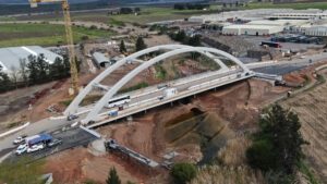
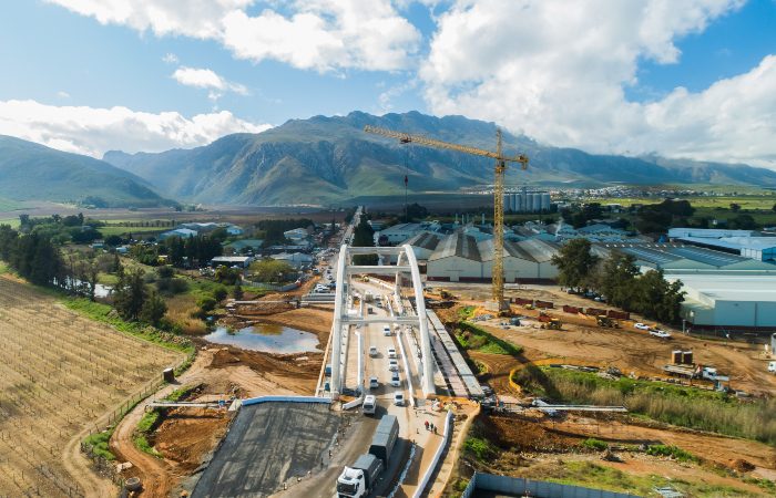
Showcasing construction at its best, the iconic Ashton Arch, designed by AECOM, sets a new benchmark for innovation as South Africa’s first concrete tied-arch bridge constructed using a transverse launching method.
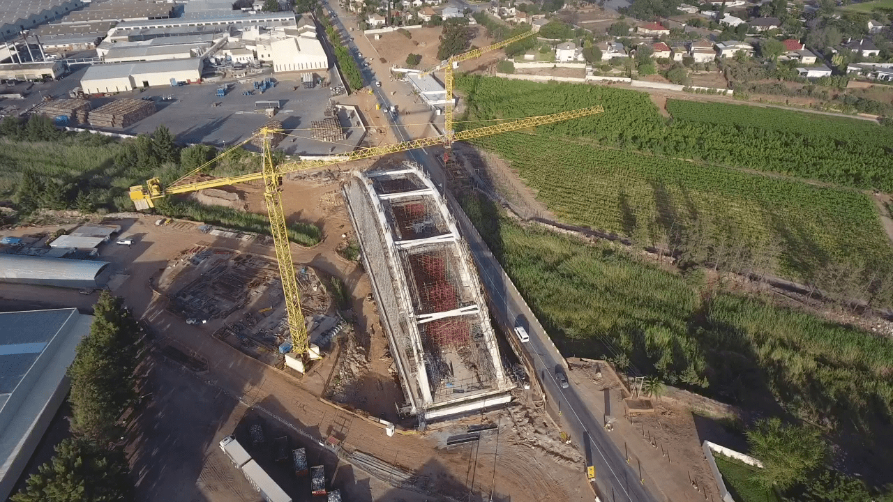
The bridge programme was executed by main contractor H&I Construction, working alongside a highly talented team of design andproduct specialists. Situated at the base of the Langeberg mountain range, Ashton is a bustling town that forms part of the Western Cape’s wine and fruit growing region. The routes passing through Ashton ultimately join the N2 at Worcester and the N1 at Swellendam, making the integrity of the town’s bridge a crucial interconnecting link. The new Ashton Arch features a cable-supported concrete deck that spans 110 m between supports, with arching ribs rising 22 m above the asphalt road surface. The twin parallel arch ribs are connected via five 15.5 m wishbone beams, providing lateral stability to the arch ribs. Post-tensioned tiebeams complete the arch’s structural form, and the final design makes provision for a dual-carriageway layout of four 3.4 m lanes and two 2.4 m sidewalks. New for old Ashton Arch replaces an existing earth-filled viaduct bridge originally constructed in 1930. This was upgraded from a single- to a dual-lane configuration in 1950. However, with the passing of the years, sedimentation build-up significantly reduced the freeboard height. During flooding, it became clogged with debris and was overtopped by the river, cutting off the town and inundating nearby properties bordering the bridge. This strongly influenced AECOM’s design, which needed to be able to cater for a vastly improved freeboard within the restrictions of the road alignment levels. Given the site constraints, the best option chosen was to construct the new bridge next to the old one to maintain uninterrupted traffic flows during construction. At an advanced stage of construction, the old bridge was then demolished, with traffic temporarily diverted over the Ashton Arch in its offset position prior to its final slide on to its new bearings and abutments. Achieving this in practice, however, required an out-of-the-box approach from the main contractor and professional team. In the end, the more than 8 000 t of reinforced concrete forming the Ashton Arch was moved transversely over 24 m in less than 24 hours to set a new South African construction record.
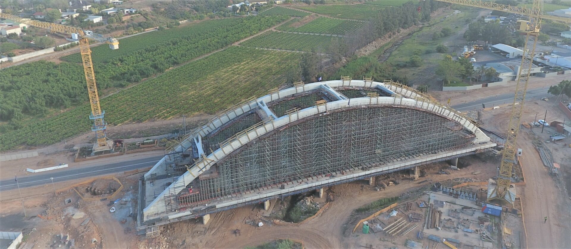
within specification. In a parallel process, the Western Cape government invited the same three contractors to price the completion of the bridge as the main contractor. H&I was awarded the project and appointed Nyeleti Consulting for the design of the transverse launch system and associated temporary works. In addition to designing the bridge for its final position, AECOM was the appointed structural engineer. Remediating the original temporary works “At the time we took over, a major portion of the deck had been built, as well as the spring points for the arch,” explains Frans van der Walt, H&I’s contracts manager for the entire project. H&I’s responsibility was to complete the bridge and move it to its final location. The steps to get there required a series of additional temporary works, which were designed by H&I. This included how the bridge would be pulled into position. As a starting point, the rehabilitation and strengthening of the existing temporary support piers was addressed and completed, as were the temporary abutments. To achieve a higher level of stability and safety on the temporary concrete support columns, the temporary works engineers specified SikaWrap-300 C for additional structural strengthening. This high-quality, unidirectional, woven carbon fibre wrapping system was used to encapsulate the head of the concrete support columns, using Sikadur-330, a structural impregnating epoxy resin adhesive. “SikaWrap-300 C has a high load capacity. It is easy and quick to apply, saving time and money on the project,” says Wayne Smithers, technical service manager at Sika. Post-tensioning The deck incorporates both longitudinal and transverse post-tensioning, which was completed before the construction of the two arches commenced. “To put this in perspective, approximately 9 477 t of longitudinal and
31 860 t of transverse tensioning was installed as per the engineers’ design requirement,” says Frank Schulz from Amsteele Systems. Amsteele Systems supplied, installed and tensioned the tendons, manufactured by DSI of Germany, as well as the 76 mm diameter Redaelli suspension cables shipped from Italy. A proprietary C hook was required to install the upper cable connection points. In total, 48 suspension cables were installed in various lengths.

The Redaelli cables were tensioned in four stages using purpose-designed hydraulic rigs to achieve the engineers’ tension
force requirements.
80 kN shoring system,” comments Gerhard Moll from Form-Scaff. Fitting both the diagonal and plan braces, Form-Scaff’s Super-Stage is quick and easy to install and strip due to click-in/snap-on features. Super-Stage further enables versatile height and width configurations. Temporary and permanent bearings Working closely with H&I and AECOM, Nyeleti Consulting’s role as the launch system designer was another key success factor. “Since this was a first for South Africa, there were many unknowns, but we put our heads together as a team to optimise the solution. At 8 000 t, this is the heaviest load I’ve ever worked with,” says Stephen Humphries, director, Nyeleti Consulting. Humphries had been involved on 10 bridges constructed using the incremental launch method (ILM) prior to the Ashton Arch transverse launch, either as the designer or temporary works designer. The Ashton Arch project adopted a similar type of temporary launch bearing used in large ILM bridges. “The exception in this case is that we employed it upside down: the temporary bearing was fixed to the underside of the deck and the sliding surface (launch pads) was at the bottom of the launch bearing,”
Humphries explains. Normally, ILM launch bearings incorporate elastomeric pads to accommodate any construction tolerances in the deck soffit; however, the load was too high in this case. Plus, the size of the bearings could not be increased as space didn’t allow for this. Following discussions with Nova Engineering Works, a bespoke bearing system was developed to support each of the four bridge corners. Each launch bearing contained two 900 mm diameter pot bearings to accommodate the deck construction tolerances.
100 mm. The bridge was then launched in this higher position. Once the transverse launch had been completed, H&I’s teams then removed the launch bearings and installed the permanent bearings, also supplied by Nova. The bridge was then lowered by around 75 mm to align with the final road level. The jacking system used to pull the bridge into position was supplied by VSL International from Switzerland, which provided input on the final method statement and quality assurance programme developed by H&I and the professional team. Go for launch The test launch took place on Friday 13 August and the actual launch began in earnest the next day. “The jacking system catered for a friction resistance of up to 11%; however, we comfortably stayed within an average range of 2% to 6%,” says Humphries. Keeping the bridge straight was vital, and H&I used various guidance tools to ensure this. These included the employment of laser markers, alignment pins on the sliding launch pads, plus ongoing survey verification. “In the end, we were within ±5 mm of where we wanted to be, which is an exceptional achievement. That outcome could only have been achieved thanks to the amazing teamwork of everyone concerned and our collective, world-class expertise,” Cirillo concludes.