Zuikerbosch Station 5A is a water purification plant under construction, located within the Rand Water Zuikerbosch Water Treatment Plant in Vereeniging.
By Kirsten Kelly
Scheduled for completion in 2024, the R3.9 billion project will purify an additional 600 Mℓ/day, which will augment the Zuikerbosch water supply capacity to the Palmiet and Mapleton booster stations. These booster stations (50 km from Station 5A) feed the greater eastern and northern parts of the Gauteng province. The new capacity of Station 5A also offers refurbishment opportunities for older potable infrastructure at Rand Water’s Zuikerbosch Water Treatment Plant.
“High water demand and inefficient water systems in Gauteng remain a concern in a country that receives approximately half the global average of rainfall. By increasing Rand Water’s supply capacity, Station 5A improves Rand Water’s network resilience and Gauteng’s water security,” explains Mahlomola Mehlo, COO, Rand Water.
As one of the oldest pump stations within the Rand Water distribution network, Zuikerbosch follows a zero effluent discharge process. This is an engineering approach to water treatment where all water is recovered; the process water is recycled back to the intake works of the plant and the contaminants are reduced to solid waste at the water residue disposal site.
A three-phase commissioning strategy has been adopted for the project. The first phase will be completed in the last quarter of 2022, where 150 Mℓ of water will be available to the Zuikerbosch overall water supply capacity. A pipeline will be connected between the filter house of Station 5A and ‘System 3’, which will give the station flexibility in operating and maintaining the existing operational plants with minimal disruptions.
The construction of the R3.9 billion project was split into subcontracts, the following of which have either reached practical completion or are within their respective stages of plant commissioning:
raw water pipeline from the Zuikerbosch Station Forebay/Buffer Dam and all other secondary pipeline works
lime slaking and dosing plant, and lime loading bay
polyelectrolyte dosing plant
activated silica dosing plant
flocculation, sedimentation and sludge pump plant
medium-voltage power supply and reticulation of Station 5A and all the associated infrastructure.
The following contracts are either under construction or still need to be procured:
filter house plant (design and construction phase)
reservoir and engine room (design and construction phase)
disinfection plant (scoping phase)
landscaping and permanent roads (scoping phase).
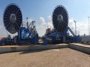
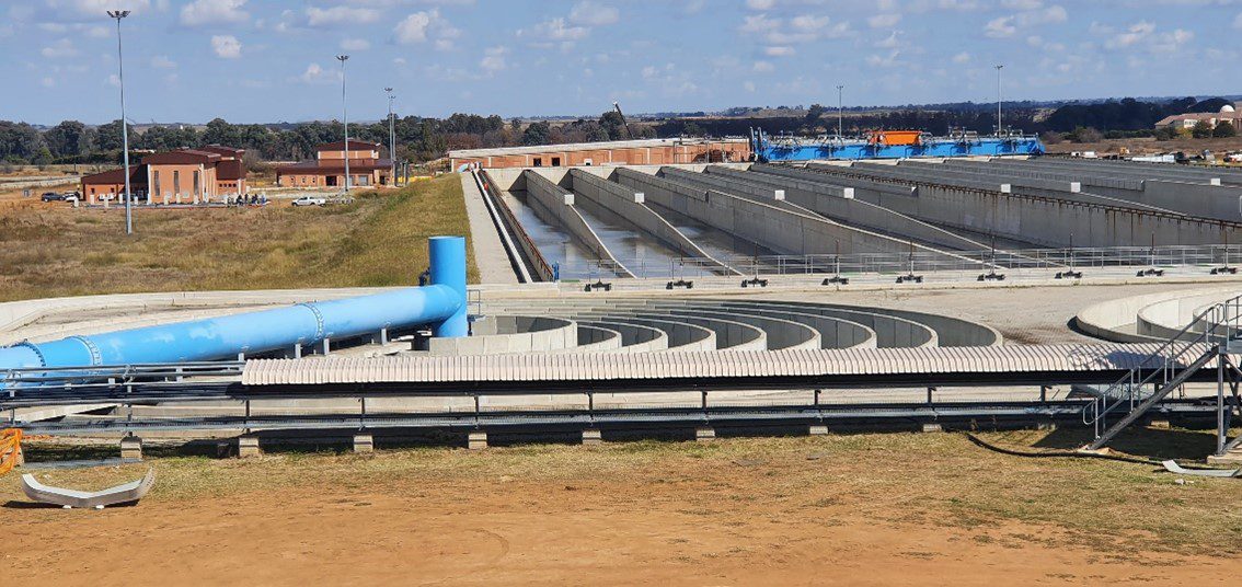
Spiral flocculators and chemical dosing plants
Raw water is pumped from the Zuikerbosch forebay/buffer dam all the way to the intake system. The pipeline then gravity-feeds water from the intake tank.
All raw water contains suspended particles that must be removed. Water from the Vaal Dam contains highly dispersed particles that tend to remain suspended for a very long period because they are colloidal. Chemical coagulants, such as calcium hydroxide (slaked lime), are used as an aid to settle these particles. This calcium hydroxide is created when calcium carbonate (raw limestone) is heated in a kiln and converted to calcium oxide and carbon dioxide gas. The burnt limestone is then crushed and water is added, in slakers, to destabilise the electrostatic charges of suspended particles in the water. A small quantity of activated sodium silica is also added to the raw water to promote flocculation.
Coagulation in Rand Water’s system is the process that destabilises the particles when the coagulants (slaked lime and sodium silica) are mixed with the raw water in about 20 to 30 seconds. This is the first process in removing suspended particles.
Flocculation is the clumping together of the suspended particles, which are destabilised by coagulation, to form heavier visible particles called floc. The floc remains in suspension as the water flows at high velocity through either spiral flocculators or baffled channel conditioning bays. In Rand Water’ssystem, orthokinetic flocculation predominates, resulting from the fluid motion at higher velocity gradients and larger particle sizes. The high pH of between 10.5 and 11 is obtained during the lime coagulation, limits algal growth and removes heavy metals, organic material, bacteria and viruses.
Station 5A has the option to use slaked lime and silica, or slaked lime and organic coagulant, depending on the quality of raw water and availability of the chemicals. To ensure the water-tightness of the three flocculation tanks, the outer walls and one internal wall were constructed in situ, the remainder of the internal walls were precast panels that were manufactured off-site.
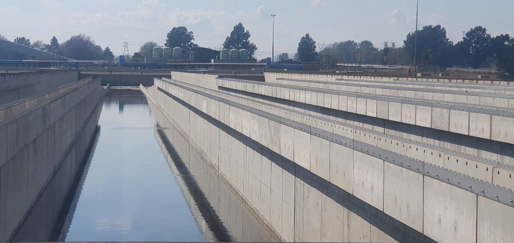
Sedimentation tanks
The sedimentation tanks stretch over 30 000 m2 and due to the soil conditions on-site, an engineered platform had to be constructed to accommodate it. Lime was used to stabilise the material, and the engineered platform was constructed, creating a 1 000 mm thick soil mattress.
A total of 60 floor panels, measuring 25 m by 25 m each were constructed. The 160 walls, each 25 m long were then constructed on the floor panels.
With a capacity of 720 Mℓ/day, providing an additional 120 Mℓ/day – should the plant size be expanded in the future – the sedimentation tanks are rectangular in shape. Water flows slowly into sedimentation tanks and the floc then settles to the bottom of the tank to form sludge. This is removed as a thin slurry containing 3% mass by volume of dry sludge. The sludge is pumped to Rand Water’s sludge disposal site at Panfontein. Here, it is dosed with an organic flocculent in gravity-thickening plants to aid the separation of the solids from the liquid. The clear supernatant fluid is drawn off and returned to the purification system. Thickened sludge is pumped on to drying beds where it is dried by evaporation.
Carbonation
The use of lime as a coagulant raises the pH of the water to about 10.5, which is very unstable and conducive to scale forming. After sedimentation, the water flows into carbonation bays where it is stabilised by adding pure carbon dioxide gas to the water. This lowers the pH to between 8 and 8.4. The carbonation plant walls at the Zuikerbosch Water Treatment Plant is 4 m high and the longest single section of wall poured was 75 m long.
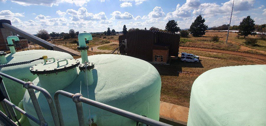
Rapid gravity sand filters
Following carbonation, the clarified water passes into the filter house where it flows through rapid gravity sand filter beds of finely graded silica sand and pebbles. This occurs under a roof to avoid bacteria from entering the treated water. The remaining suspended particles are removed and ferric chloride may be added prior to filtration to enhance the process. There are two galleries at Rand Water’s filter house – each with 32 filters.
The water leaving the purification plant is disinfected with chlorine to kill microorganisms, bacteria and viruses that may be present in the water. The free available chlorine concentration must be between 0.8 Mℓ and 2.5 Mℓ, depending on the raw water quality to ensure that all pathogens are killed. Once water from the filter house is chlorinated, it goes to the reservoir.
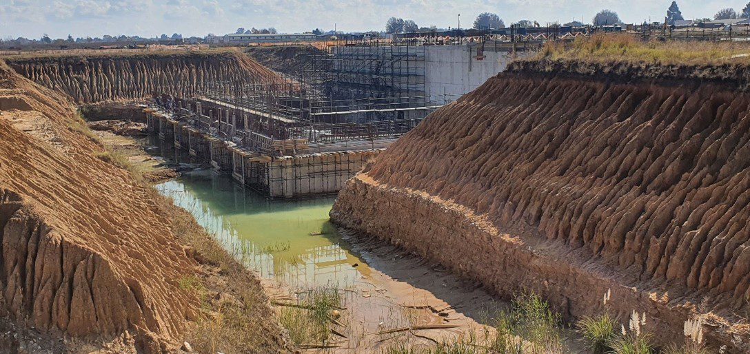
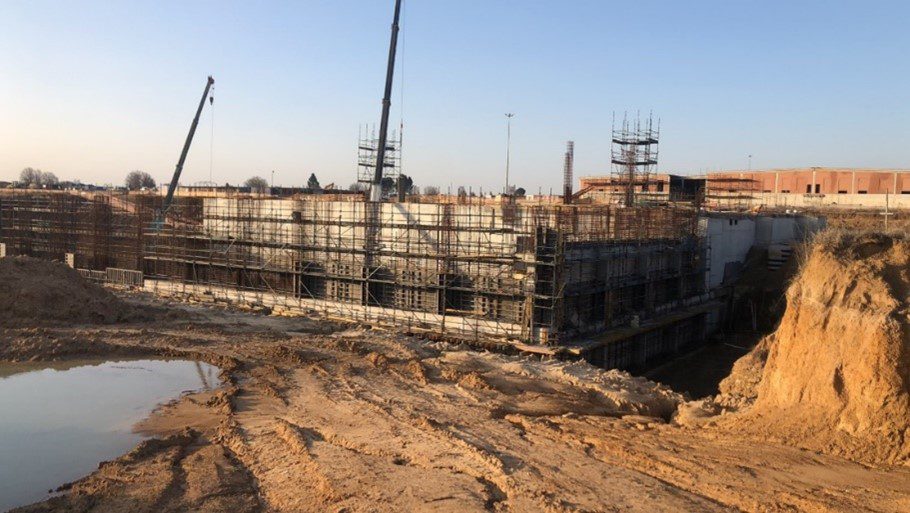
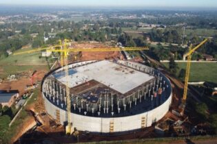
Engine room and reservoir
Termed as the ‘heart of the water treatment plant’, the engine room (as well as the reservoir) is constructed by King Civil Engineering Contractors. While 600 Mℓ/day of water will go through the pump station, it is designed to handle an impressive 1 000 Mℓ/day of water – creating 400 Mℓ redundancy.
“Due to the gravity-fed system, the engine room and reservoir are constructed at the lowest level and are the last part of the project. Rand Water has an extremely high water table, and all of the run-off water drains towards our site. As contractors higher up completed their work and stopped using dewatering pumps, we had excess water on our site,” explains Andre Bosman, contracts director at King Civil Engineering Contractors.
A 300 m long HDPE pipeline is installed, where water is continuously pumped out of the site.
With the high water table, buoyancy of the structure was an important design consideration. “Part of the engine room is 12 m below the ground. The original design of the structure was extremely heavy to prevent buoyancy. After further geotechnical investigations, the decision was made to use a less costly design and build a lighter structure with ground anchors to counter the weight,” adds Bosman.
The pump station is designed for six pump sets, five of which have been supplied by Rand Water. They will all be electronically controlled by a programmable logic controller (PLC). The pipe work in the engine room will eventually be connected to feed into the Rand Water distribution network.
The reservoir acts as a storage facility for the treated water. To minimise joints and ensure a watertight reservoir, 7 m to 10 m high walls were cast in a single pour.
From the reservoir, water is pumped into the common sump in the engine room, which will prevent movement of water that can affect the pumps’ efficiency. Water will then be pumped into the 3 500 km Rand Water distribution network via two 2.1 m diameter outlet pipes that still have to be installed. Ten 1 500 m diameter valves, that are 6 m high and weigh 26 t also need to be installed.
“As the pump station feeds water to two major pipelines, the pump and valve configuration allows water to be pumped to either of the two pipelines should there be an issue with one of the pipelines or if some of the pumps are offline. There is an impressive amount of redundancy in the system,” states Bosman.
There is a dedicated substation from the Eskom electricity transmission station, main underground transmission lines to Station 5A substation, and all associated infrastructure to enable the safe interconnected electrification of all plants.
Reservoir
Concrete
3 213 m3
Formwork
534 m2
Reinforcing
8 491 t
Rock Anchors
91 nr
Engine room
Concrete
5 798 m3
Formwork
19 604 m2
Reinforcing
1 229 t
Rock Anchors
70 nr
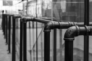
Pipelines
Murray & Dickson Construction (M&D) was awarded the R234 million pipeline contract in 2019. “The project was delayed slightly due to Covid-19 and is reaching completion this month. We laid all the pipelines within the Zuikerbosch pump station and pipelines linking the forebay to Station 5A and from Station 5A to the new works, as well as interconnections of some of the pipelines,” explains Martin van Aswegen, head: Pipelines Division.
Pipe diameters varied between 1.5 m and 2.5 m, with trenches as deep as 10 m. A total of 2 600 m of pipeline was laid: comprising 1.3 km of raw water pipeline, a 1.5 km water line and a 450 m carbonation line. The contract also included all excavation, trenching, backfilling and welding, as well as the supply and installation of gate valves, air valves and scour valves. They also installed (with added protective coating for corrosion protection) manholes and chambers, and added cathodic protection to the pipes.
The steel pipelines were chosen, due to their durability. “These pipelines were laid utilising multiple side-boom cranes in tandem lifts, with each pipe weighing in at over 25 t. There was a section where we laid a 2.1 m pipe beneath two 2.1 m pipes,” adds Van Aswegen.
Double 1 400 NB wedge gate valves with a 2 500 NB special manifold (reducing to a 1 400 NB section) that weighed 26 t was installed at the forebay connecting chamber. With its own ISO 3834-2 certified fabrication factory, M&D could rapidly manufacture its own pipe fittings and manifolds, and owns all specialised equipment required for pipelaying. M&D is also ISO 9001, ISO 14001 and ISO 45001 compliant.
“There are 14 electrically operated valve actuators that can remotely control and monitor pressure. A drop in pressure is usually an indication of a burst pipe and these valves will assist Rand Water in proactive, speedier repairs and maintenance, minimising water losses. M&D also installed fibre-optic lines for communication between the electrically operated valves and the control room,” says Jacques de Coning, senior contracts manager, M&D.
All welding on the pipelines was done according to standard. Once the coatings are completed, M&D submits footage of the inside of the pipes taken by a CCTV camera and conducts a pressure test.
A portion of the work was completed by local subcontractors, where M&D provided mentorship and management. A total of 80 local people were used by M&D and 40 took part in a skills development initiative.
The site was congested and M&D had to consistently interface with other contractors and Rand Water in order to lay pipelines without disrupting Rand Water’s operations. There were also high water tables, and pumps had to permanently remove water from the trenches into a nearby dam.
One of the great achievements of this project was the four big hot taps that were completed by a specialist contract overseen by M&D. There were two 1.4 m connections to a 3 028 m diameter pipeline (7 000 kPa) near Pump Station 4 and two 1.5 m connections to a 2.1 diameter pipeline. “This is the largest hot tapping works on a waterline in South Africa,” says De Coning.
Hot tapping (under pressure cutting) is the method of making a connection to existing piping without interrupting the line. Once the T-piece is welded, a valve is connected and specialised drilling equipment is connected on to the valve. The valve is opened, a pressure test is done and the equipment cuts a portion out of the pipe. The valve is closed and equipment is removed, completing the tie-in.
Quantities of pipeline work
Total pipeline length: 2 600 m
Clear and grub: 2 600 m
Trench excavation: 44 000 m3
Removal of hard rock: 10 000 m3
River sand bedding: 21 000 m3
Installing of pipe: 3 600 m3
Concrete works: 7 000 m3
Manholes and structures: 12
Valves: 45
Hot tap connections: 4
Redundancy
“Regular maintenance helps to identify and resolve minor issues before they become serious and costly hazards. Like all machinery, equipment in a water treatment plant can fail. This can happen slowly over time or suddenly and if left unattended, the consequences could be costly. Maintenance is therefore a priority for Rand Water and Station 5A has been designed with a huge amount of redundancy,” Mehlo adds.
Rand Water had to strike a balance between cost of ownership and mitigating the risk of reduced supply from unexpected machinery failure and scheduled maintenance, as well as operational efficiencies.
While Station 5A is a gravity-fed system, water still needs to be pumped 50 km to the Palmiet and Mapleton booster stations. Therefore, large pumps are required. Additional pump capacity has been supplied and suitable valve configurations are provided to facilitate the removal of pumps and motors for planned and unplanned maintenance.
Furthermore, standby power is provided for the intricate dosing, electromechanical and automation systems.
Capacity was also added to the flocculators, sedimentation tanks and filters. This means that cleaning and inspection can occur on a rotational basis with little impact on operational duties and no impact on water quality.
Training, development and SMMEs
“I am incredibly proud that Station 5A has been managed by a young project management and engineering team, and 41% of these roles are held by women. The team has performed exceptionally in managing numerous project challenges under difficult circumstances (Covid-19) to keep the overall programme on track, while reducing delays and negative financial impacts on Rand Water,” states Mehlo.
Due to Rand Water’s Enterprise Development and Socio-economic Policy, the local community and SMMEs were involved since project inception. Various contractors on the project have commended Rand Water for its excellent social facilitation programme and community engagement.
Founded in 1886, Johannesburg began as a mining shanty town. An increasing concern over water followed the euphoria from the discovery of gold. In 1903, Rand Water was formed by individuals and institutions who instead of pursing riches,...
Gauteng’s water supply has been a topic of concern throughout 2024 since Rand Water’s October announcement that water supply might face critical issues if demand and usage do not decrease there has been increasing scrutiny of the water board and...
Rand Water is set to conduct major maintenance work on the bulk water supplier’s infrastructure from 3 June to 21 July 2025, which will impact on some of Johannesburg Water’s systems. The objective of the maintenance is to improve plant...