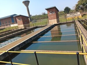
The operation of a pulsator clarifier can be optimised with regards to suction lift and drop times. This can be done by considering the varying turbidity of raw water (low versus high settleable solids) as well as controlling the sludge blanket depth.
By Kimon Padayachee, WISA member A pulsator clarifier plays a crucial role in the operation of the water treatment plants, aiding in the removal of suspended solids and facilitating the clarification process. It is a simple type of up-flow tank, of which its effectiveness depends on the formation of the sludge blanket. With its hopper-bottomed tank, the pulsator clarifier allows flocculated water to flow upward through the sludge blanket in alternating cycling or pulsating flow stages of suction lift and drop times. This is done via a vacuum pump that induces fluid motion and enhances the settling of suspended solids. Pulsating flow cycle The pulsating flow cycle consists of two phases:- suction lift phase (usually 60 cm – 100 cm)
- bed expands uniformly
Higher settleable solids sources require longer suction lift times (40 – 60 seconds) to allow pulsators to effectively draw in the solids-laden water. This case is indicative of a higher concentration of suspended solids and longer suction lift times that are necessary since as raw water passes through, the suspended blanket seizes the particles and clarified water travels upwards to the top of the unit.
High velocity of flow through the sludge blanket creates greater resistance, high degree of particle collisions between primary flocs presents in coagulated water and secondary flocs present in the sludge blanket which results in a higher flocculation energy that leads to a consistent and stable sludge blanket formation. Flocculation energy refers to the energy required to promote the aggregation and growth of particles into larger flocs during the flocculation process. The flocculation energy process occurs under the hydraulic pulsation mechanism where there is a periodic variation of water levels within the clarifier using hydraulic pulses or surges as described above. These pulsations create a back-and-forth flow pattern within the clarifier, aiding in the flocculation process by enhancing particle collisions and floc growth. By extending the suction lift time, pulsator clarifiers have additional opportunity to thoroughly extract the suspended solids from the raw water. The increase in volume concentration of sludge blanket improves the flocculation efficiency process which occurs within sludge blanket. It is also advisable that during the occurrence of high settleable solids in the raw water, the plant should not utilise a Streaming Current Detector (SCD) analyser for coagulant dose control. An SCD analyser is commonly used in water treatment plants to measure the electrical charge or zeta potential of particles in the raw water. It assists in monitoring and controlling the coagulant dose by providing real-time response on the effectiveness of the coagulation process. However, under conditions of high settleable solids, utilising an SCD for coagulant dose control is not suitable for the following reasons:- There are a significant number of particles present in the raw water, which interferes with the accurate measurement of SCD analyser due to sensor fouling. The suspended particles can affect the electrical conductivity and charge distribution within the analyser, leading to inaccurate readings and unreliable coagulant dose control. During the April 2022 flooding event, at a raw water turbidity of 3000 NTU, the SCD analyser provided a coagulant dose of 128 ppm whereas a jar test provided an optimum dose of 60 ppm. This contribution of increased coagulant overdosing immediately led to the formation of small compact flocs which remained suspended in the pulsator clarifier and resulted in complete cloudiness at the surface. In addition, this also caused filter blinding resulting in minimal effectiveness in removing solids and increased final water turbidity. In order for the treatment process to continue successfully, the ‘overdosed’ water at each process train was discarded to the sludge plant.
- Inadequate Charge Detection: The SCD relies on the measurement of the electrical charge carried by the particles in the raw water. However, under conditions of high turbidity, the particles may have irregular shapes, sizes, and compositions, making it difficult for the SCD to accurately detect and measure their charges. This can result in inconsistent or incorrect readings, leading to ineffective coagulant dose control. Under the above conditions, coagulant proportional dose control is recommended where the jar test optimum coagulant dose can be used as the set-point value. It is recommended to conduct cascade tests and jar tests every hour and two hour respectively under high settleable, solids raw water conditions until the raw water turbidity stabilises.


