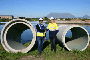
This feature seeks to outline the various aspects of horizontal directional drilling (HDD) in South Africa, contextualised by three case studies, namely, Berg River Duct Installation, Diep River Water Pipeline Installation and the Bulk Water Main Installation under various roadways for the Mossel Bay Desalination Plant Project.
Case study 1: Berg river duct pipeline installationLocation: Berg River, Velddrift (approximately 145km north of Cape Town)
Diameter of pipeline installed: multi-duct – 4 x 160mm diameter HDPE ducts (installed in two parts)
Length of installations: 168m and 164m
Obstruction traversed: Berg River – approximately 140m wide and 9m deep (approximate measurement taken along the bore path)
Client: Local power utility
Main contractor: Racec Electrification
Drilling contractor: TT Innovations The installation of the duct pipelines under the Berg River formed part of an initiative to upgrade the existing power supply to the Velddrift area. Two existing power feeder cables, suspended below the Carinus Bridge, served as the main power supply to the town and local fish factories. As this section of road (including the bridge) was scheduled for future upgrading, it was decided to install the new power supply cables beneath the river instead. Apart from the obvious construction constraints with regards to trenching across a river of this magnitude, the importance of this water body to the local fishing industry, tourism and its ecology played a major role in the decision making process regardingthe method of construction. Any diversion of the river course or activities which could cause flooding of the river banks would result in dire consequences for both the natural habitat and human inhabitants along the river. Incremental measurements of the river invert were taken using a boat and survey equipment. The depth of the river was determined to be approximately 9m at the deepest point (due to the close proximity of the sea and subsequent tidal nature of the river, a mean water level between low tide and high tide was used for the depth calculation). A bore plan was derived using this data with a maximum pilot bore depth reaching 3 m below river invert level. The initial pilot bore (150m) proceeded without incident, apart from intermittent navigational signal losses and, after various steering corrections, reached the target.Reaming commenced immediately thereafter. The drill rods were attached to the rear of the reamer, trailing it during reaming. During one of these reaming stages, the spindle of the reamer detached due to a suspected bearing failure, causing metal fragments to be left behind in the bored tunnel. The tunnel was consequently abandoned and a new pilot bore installed adjacent to the previous tunnel. With the new tunnel successfully bored and all the reaming stages completed,the original 3-pipe, 160mm diameter HDPE duct configuration was attached to the reamer and inserted. The installation however ground to a halt just as the reamer and product pipe passed the pivot point along the final incline of the curved bore bath. The rapidly increasing forces had exceeded the rig’s pulling capacity. Later investigation revealed that this was largely due to the bentonite being degraded by the high salt water content of the insitu soil. The drilling fluid (water and bentonite mixture) could therefore not perform its primary function of transporting the soil cuttings to the surface. The resultant soil builds up in the tunnel (increasing the friction along the pipe), in conjunction to the steep final incline, ultimately led to the rapid increase in pulling force. The salinity of the ground water was never considered as the Berg River is a freshwater river. A nearby freshwater lake also seemed to support this notion. It was however later learned that the river becomes salty at high tide and fresh again during the low tide. After numerous unsuccessful attempts at getting the pipe unstuck, the only apparent solution was to free the product pipe from the reamer. To do this, the contractor manufactured a device that attached to the end of the drill rods, which extended a set of cutting blades when forced outward by the drilling fluid pressure. The drill rods and cutting head were then inserted from the rear of the HDPE pipe.With the blades extended, the drill rods were rotated, severing the HDPE pipe and releasing it from the reamer. This option rendered the HDPE pipe unusable as any attempts to remove the partially installedpipes resulted in over-stretching which deformed and restricted the useable cross-sectional area of the pipe. The reamer was retrieved and re-used. Despite these trying circumstances and set-backs, the contractor persisted. Salt water compatible bentonite was used for this attempt and the bore path lengthened to 168m to allow for a flattened incline curve. It was also decided to increase the tunnel size and change the pipe arrangement from a 3-pipe to a 2-pipe configuration. The client duly elected to also install a fourth duct for future use. These measures were successful and culminated in two successful installations measuring 168m and 164m each.
Case study 2: Diep River water pipeline installation
Location: Adjacent to Gie Road, Table View – Cape Town
Diameter of pipeline installed: 315mm diameter HDPE PN12
Length of installation: 200m
Obstruction traversed: Diep River – seasonal river and wetland ecosystem
Location: Mossel Bay, Southern Cape (approximately 392km from Cape Town when heading east along the coast)
Diameter of pipelines installed: 800mm diameter
Length of installations: 46m and 50m
Obstruction traversed: Ywo main roads – Louis Fourie Road and Alwyndal Road
Client: Mossel Bay Municipality and PetroSA
Main contractor: EntshaHenra
Drilling contractor: TT Innovations (Pty) LTD Owing to a spate of droughts in the Southern Cape Area, the local municipality of Mossel Bay and private sector stakeholders financed and approved the construction of a desalination plant along the nearby coastline. This consequently necessitated new bulk water pipeline installations (greenfields) – which also crossed two main roads. The local roads’ authority, however, insisted on the use of trenchless technology for the main road crossings. HDD was decided as the trenchless solution to be employed and various contractors were invited to submit bids for the installation of these works. The project consulting engineers selected the approved drilling contractor on the basis of their technical ability and previous project experience. The pilot bore under Alwyndal Road commenced without incident and was completed on schedule. Operations, however, ground to a halt during the early hours of the morning when the effluent water supply valve failed causing a disruption to the supply. Without an alternative water source, work was halted until the supply could be restored.
 By midday the following day, the water supply was restored and drilling re-commenced. Reaming proceeded at a slow but steady pace, with the reaming rate of progress slowing as the reamer size increased. A temporary holding ‘pond’ was created adjacent to the drill site to house the drilling mud spoil and a TLB was utilised to remove the drilling mud from the drilling pits.
Due to the large diameter of the pipewhich needed to be installed, the frictional force caused by buoyancy had to be counteracted. Instead of the conventional closed front end, where the pulling head connects to the pipe, it was decided to leave this front end open – thereby creating an open-ended pipe and cancelling any buoyant forces.
After installation, any drilling mud or spoil which collected within the pipe could be removed by conventional pipe cleaning methods. Further to this, the shallow cover over the pipe also increased the risk of drilling fluid escaping to the surface through the above soil layers due to excessive fluid pressures within the tunnel (frac-out). Once all the reaming stages were successfully completed, the 800mm diameter HDPE pipeline was installed.
The actual installation duration of the pipe was minimal when compared to the various reaming stages. Using the drill rig, the 630mm diameter HDPE product pipe was inserted within the 800mm pipe. The product pipe simply displaced the drilling mud and no additional pipe cleaning was required. The Louis Fourie installation proceeded in similar fashion, with the only delay being caused by mechanical failure on the mixing tank.
by Neil van Rooyen


