In order to accommodate the expected additional sewage flow from new developments in the GaMohale and Magaliesburg areas, the Mogale City Local Municipality embarked on an extension of the Magaliesburg WWTW.
Keeping up with community demands Pro-Plan Consulting Engineers were initially appointed by the Mogale City Local Municipality (MCLM) to provide full engineering services for the design and construction of the required extension at the Magaliesburg WWTW from 3Mℓ/day to 4Mℓ/d. Since the MIG registration, the additional flow has been identified and it is estimated that the extension required will be two 3Mℓ/d modules i.e. an additional 6Mℓ/d, split in two phases. The following processes are underway: Environmental Impact Assessment (EIA) scoping report: the EIA is being conducted by external environmental consultants Geotechnical investigation: a geotechnical investigation will be carried out and a final report will be compiled and submittedTopographical survey: a topographical survey of the existing WWTW as well as the area available for the new module has been carried out
Licensing of the WWTW: the licensing process will be done in conjunction with the EIA and will be submitted to DWAF by the environmental consultants Existing infrastructure
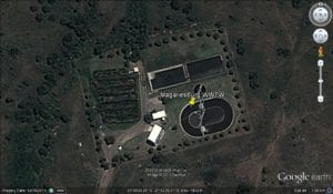
The existing Magaliesburg WWTW was constructed in 2002 by the Western Gauteng Services Council. The works was constructed to have a capacity of 1 100 m³/day and utilises an activated sludge process (ASP). The biological treatment system comprises of the following components:
• inlet works consisting of a mechanical screen and de-gritting system
• flow measurement chamber
• race track type biological reactor
• ‘Dortmund’ type clarifier
• sludge lagoons
• sludge recycling
• constructed wetlands / reed beds
• disinfection (chlorine)
The majority of the flow entering the works is pumped with three transferring pumping stations, which is graphically presented in Figure 1. Tankers are also used to transfer sewage to the works with a ‘make-shift’ drop-off point provided outside the boundaries of the WWTW. Flow measurements taken downstream of the inlet works indicates that the plant has not been operated close to its capacity yet. Figure 2 represents flow measurements taken since the plant has been operational in 2002. The poor performance of the WWTW is thus not a result of the inflow exceeding its capacity.The dire situation that the WWTW is in can however be attributed to the poor condition of the mechanical equipment. A site visit conducted in September 2009 revealed that most of the mechanical equipment is out of operation and in need of maintenance / refurbishment, which Mogale City has addressed. Infrastructure development goals
The existing Magaliesburg WWTW is a relatively small facility with limited redundancy and back-up, and the plant upgrade and expansion will create additional infrastructure redundancy and the necessary back-up facilities. The aim of the project will be to improve the reliability of the plant operation and performance. The flow arriving at the treatment plant emanates from properties in Magaliesburg and GaMohale and is predominantly domestic in nature, although a few small industries contribute to the hydraulic and organic load to the WWTW.
The project will aim to utilise robust, efficient and reliable treatment technologies, which have a proven record of accomplishment with MCLM. At the same time, new technologies, which can serve the works facilities for the next decades, will be considered. The MCLM supports the initiatives being rolled out to provide infrastructure that addresses the efficient use of electrical energy and the selection of treatment technologies will be influenced by energy efficiency. It is a target to reduce energy usage per unit of wastewater treated, with the plant expansion project. In addition, the project will consider the environmental footprint and will mitigate the potentially negative impacts including treated wastewater discharge quality, uncontrolled wastewater discharges during unusual WWTW operating conditions, such as during electrical power interruptions, and the release of foul odours, which is mainly related to the sludge handling process.
Project design
The expected flow for the developments is 5.4Mℓ/d. It is therefore recommended that that plant be extended by 6Mℓ/day, with two 3Mℓ/d treatment trains.
MCLM is monitoring the effluent at various stage of the process on a weekly basis. Water quality data was received from MCLM and analysed to obtain a clear picture of the quality of the incoming flow as well as the performance of the treatment process. The data received spans the period October 2002 to July 2009. Table 1 indicates the weekly minimum, maximum, average and 95th percentile of key constituents measured.
pH TAlk (mg/l CaCO3) Cl (mg/l) EC (mS/m) TDS (mg/l) NH3-N (mg/l) NO3-N (mg/l) O-PO4 (mg/l as P) T-PO4 (mg/l as P) COD (mg/l) SS (mg/l) TKN (mg/l) TKN/
COD
Ave 8.23 361.89 74.58 103.93 401.13 64.63 20.99 10.03 14.03 919.35 580.43 81.80 0.12
Min 6.87 67.49 10.80 22.40 145.00 0.07 0.16 0.17 0.21 24.00 10.00 1.75 0.01
Max 9.47 1236.68 330.52 308.00 1286.00 391.48 3233.11 26.97 593.00 7979.0 24730.0 318.06 0.70
95th percentile 9.08 771.94 155.37 207.90 672.20 164.32 51.43 19.79 22.74 2285.8 1023.50 186.36 0.23
70th percentile 8.60 399.83 83.70 117.25 437.60 76.40 3.10 12.09 14.36 988.80 388.00 97.72 0.13 For the size of the developments that will be served, the peak factors and resulting peak flows as indicated inTable 2 will be accommodated in the design of the extension of the WWTW. The design will thus accommodate the attenuation of these flows as they vary throughout the day. Table 2: Expected flows
Flow Rate Peak Factor Existing
1.1 Ml/d Extension of 6 Ml/d Ultimate Capacity (7.1 Ml/d)
Average dry weather flow (ADWF) N/A 1.1 6.0 7.1
Peak dry weather flow (PDWF) 1.7 1.87 10.2 11.97
Peak Hourly Flow (PHF) 2.5 2.75 15.0 17.25 The flow will continue to be predominately domestic in nature. It was noticed that the organic loading in the incoming flow was excessively high. After investigating, the causeof the spikes in data was pinpointed as honeysuckers dumping their loads right at the entrance to the plant. This has since been slightly relieved by insisting that the dumping be done further upstream of the plant.However, it is recommended that water be provided to dilute this flow in order to minimise the organic loading on the treatment works. Another option is to discontinue the practice as the minimum level of service for the area is water borne sewage reticulation. Process overview
• Raw sewage entering the works will be split ahead of the existing inlet works where 1Mℓ/d will be routed to the existing works and 6Mℓ/d will be routed to the new works. The 6Mℓ/d inlet works will be built in Phase 1
• A new 2Mℓ balancing tank will attenuate flows entering the new extensions
• Internal recycles will comprise of the following:
o from aerobic to anoxic (a-recycle) — 1:6 (average)
o from anoxic to anaerobic (b-recycle) — 1:1 (average)
o underflow from the clarifier will be recycled back to the anaerobic zone 1:1 ratio (average) (s-recycle) via the recycle PS
• Effluent (MLSS) from the activated sludge reactors will flow to the clarifiers
• Overflow from the new clarifiers will be collected and transferred to the chlorine contact channels
• Waste sludge from the aerobic zone and clarifier will be wasted into a sludge collection box, thickened in two sludge thickeners, before entering the existing sludge lagoons
• Several alternative flow routes will be incorporated in order to allow for the bypassing of certain units in the case of maintenance or repairs. Mechanical equipment will be selected to be easy to operate and to keep a limited number of spare parts on-site.


