Lined containment facilities are at the heart of modern waste management and pollution control. They serve as the critical barrier between potential contaminants and the surrounding environment, preventing the migration of pollutants into soil and groundwater. Engineered lining systems, incorporating geomembranes, are designed to ensure this containment remains intact.
Yet, the industry’s reliance on technology such as electrical leak location (ELL) has, in some cases, led to misplaced confidence that this final testing step can compensate for shortcomings elsewhere in the design or construction process. Electrical leak location is a proven and powerful quality assurance tool, capable of identifying defects in geomembrane liners with remarkable precision. However, ELL is not a substitute for good design, sound construction practice, and rigorous quality control. Instead, it must be integrated as part of a broader culture of quality that spans every phase of a project, from initial concept through to commissioning.The role of ELL in modern containment design
Over the last decade, ELL has become widely recognised by regulators and designers as an essential element of quality assurance in the construction of lined facilities such as landfills, tailings storage facilities, and wastewater ponds. The technology provides a means of locating and repairing breaches in geomembranes, often caused during installation or cover placement, that would otherwise go undetected. At its core, the dipole method of ELL operates on simple electrical principles. A voltage source is connected between a current injector placed within the covering material and a grounded electrode positioned outside the lined area. The geomembrane acts as an insulator; any current detected flowing through the liner indicates a breach. Using a dipole unit to measure electrical potential across a pre-determined grid, technicians can locate these breaches with high precision and in real time, facilitating repair before the facility is commissioned. When properly executed, the method can detect punctures as small as a few millimetres, providing an invaluable layer of quality assurance. However, the authors note that its success is not guaranteed simply by conducting the test. For ELL to function effectively, the materials, design, and field conditions must all be compatible with the technology’s scientific and practical requirements.Design compatibility: building for testability
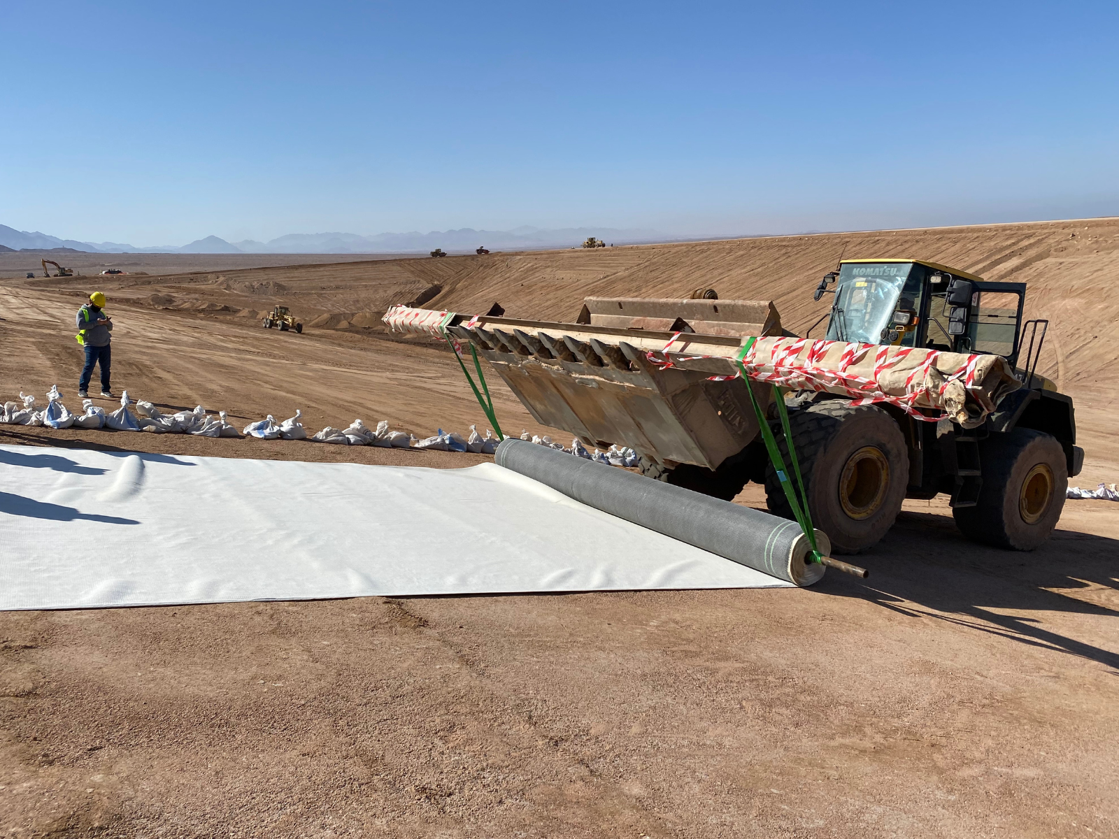
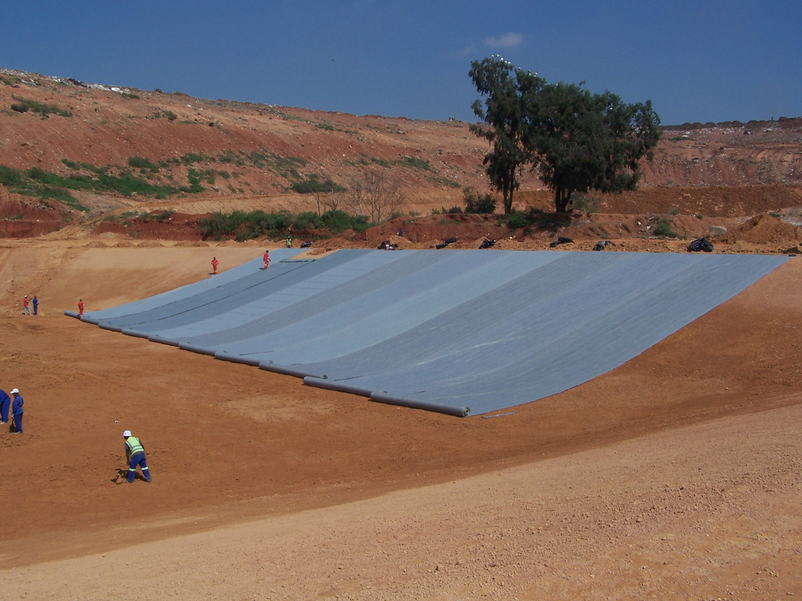
Geosynthetic linings have been used since the 1950’s and are just as relevant today
The ideal scenario is a moderately conductive environment with well-controlled moisture content; many specifications reference a minimum of 8% moisture in the cover materials to achieve this.Equally important is electrical isolation. The materials covering the geomembrane should behave as an isolated ‘island’, entirely separated from any grounded material outside the lined area. If the current injected into the covering layer can escape through unintended pathways, such as contact between fill material and in-situ soil, grounded pipework, or improperly isolated anchor trenches, the results can be unreliable or misleading. Designers must also consider cover thickness and homogeneity. Practical experience indicates that the covering material above a geomembrane should not exceed 600 mm in thickness (and certainly no more than 1,000 mm), as deeper or highly variable layers reduce sensitivity and accuracy. Similarly, uniformity in material gradation and moisture content helps maintain consistent readings across the survey grid. These design principles extend to the treatment of specific structures. Anchor trenches should be configured to maintain electrical isolation between the liner and adjacent ground, while any internal berms, ramps, or drainage structures must be designed to prevent conductive bridging across the containment boundary. For multi-cell facilities, temporary isolation trenches between cells can ensure accurate testing prior to interconnection. Critically, specifications must be project specific. While ASTM D7007 and ASTM D8265 provide valuable guidance on ELL procedures for covered geomembranes, they are not intended as prescriptive, one-size-fits-all standards. Site-specific factors such as geometry, materials, climate, and liner configuration require thoughtful adaptation of these standards to ensure meaningful results.
Dipole testing in practice
In the field, dipole testing relies on a systematic grid-based approach. The surveyor moves the dipole unit across the surface in measured intervals, recording electrical potential at thousands of data points. The dipole spacing, typically around one metre for cover layers up to 600 mm thick, is critical. Smaller dipole spacing allows for greater resolution and increases the likelihood of detecting small, localised leaks. Some specifications, such as those developed by Leak Location Services Inc., recommend a data density of at least 3 000 points per acre, with dipole spacings between 0.9 and 1.1 metres and survey lines spaced no more than 1.5 metres apart. This density ensures that the smallest possible damage can be located without repeated re-surveys, saving both time and cost. Once leaks are identified, they must be uncovered, inspected, and repaired under controlled conditions. It is best practice to re-test the repaired area immediately, as large breaches can mask smaller ones nearby. A systematic approach, locating, repairing, and verifying sequentially, ensures that no defects remain undetected before final sign-off.Site preparation: the foundation of accuracy
 Even the most sophisticated technology will fail without proper site preparation. For ELL to produce reliable and repeatable results, the test area must be well prepared and adequately conditioned.
The area should be fully completed and quality-checked before testing begins, including all relevant CQA inspections, seam testing, and repair work. Electrical isolation must be verified, ensuring that there are no unintended conductive paths between the test area and surrounding ground or structures. Common pitfalls include metal piping, grounded pump bases, concrete structures penetrating the liner, and water-filled risers, all of which can interfere with current flow and distort readings.
Even the most sophisticated technology will fail without proper site preparation. For ELL to produce reliable and repeatable results, the test area must be well prepared and adequately conditioned.
The area should be fully completed and quality-checked before testing begins, including all relevant CQA inspections, seam testing, and repair work. Electrical isolation must be verified, ensuring that there are no unintended conductive paths between the test area and surrounding ground or structures. Common pitfalls include metal piping, grounded pump bases, concrete structures penetrating the liner, and water-filled risers, all of which can interfere with current flow and distort readings.
Moisture management is equally critical. The materials above and below the geomembrane must be sufficiently hydrated to provide sufficient conductivity, but not saturated to the point of creating isolation breaches.In arid climates, this may require pre-hydration of subgrades or geosynthetic clay liners (GCLs) prior to covering. Conversely, excessive rainfall can flood isolation gaps, creating unwanted conductive bridges. Proper water application during site preparation often demands logistical planning, adequate water supply, pumping capacity, and supervision to maintain consistent conditions throughout the survey. Uneven hydration can lead to false readings, delays, and increased costs.
Construction practices: Integrating ELL into the quality process
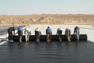
The success of ELL depends as much on construction discipline as on design or testing. The authors emphasise that a culture of quality must underpin the entire process. This includes careful control of vehicle traffic across liners, strict adherence to CQC procedures during cover placement, and close coordination between contractors and quality assurance teams. Poor workmanship or inadequate supervision can result in significant damage to geomembranes, particularly during the placement of stone drainage layers or heavy protective fills. Excessive wrinkles, improperly overlapped geotextiles, or heterogeneous materials can all interfere with the electrical continuity required for effective testing. Moreover, the assumption that a post-construction ELL survey will compensate for such issues is misguided. The technology is most effective when it forms part of an integrated quality assurance programme, supplementing, not replacing, good construction practice.Quality assurance and the limits of detection
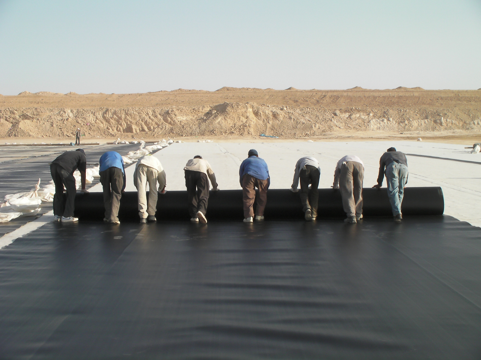
Placing geomembranes, a vital part of the landfill and one that cannot afford to be compromised through holes
Cost, risk, and the value of integration
From a cost perspective, ELL represents a relatively small investment for a potentially large return. Studies indicate that leak location surveys typically account for less than one percent of total project costs, yet they can prevent extensive environmental damage, regulatory penalties, and costly remediation efforts. However, the return on this investment depends on proper implementation. An inadequately prepared or poorly executed survey provides a false sense of security, arguably more dangerous than no survey at all. Integrating ELL into the design phase, ensuring full compatibility across materials and construction methods, and maintaining rigorous quality assurance throughout are the keys to achieving genuine risk reduction.The path forward: quality by design
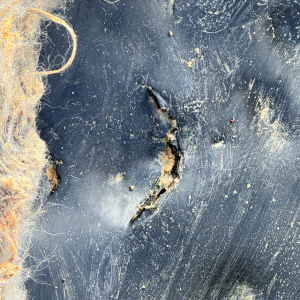
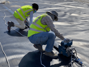
Small puncture detected using electrical leak
location

Ettienne de Jager, project manager
at Envitech

Brendon Jewaskiewitz, managing
director of Envitech